Tuesday, July 4, 2023

Rewire Vintage Singer Light Fixture (15-90, 15-91 Series)

Rewire 15 Series Singer Light Fixture


I always rewire the Singer light fixture when rewiring the motor.  Fifty to eighty year old wiring is all ready to be replaced.

I'm also having great luck with the LED replacement lamp (no heat, long life, more light).

Supplies Needed:

Solder
Flux
Soldering Iron
Desoldering Tool
18 gauge 18/2 SPT-1 wire (lamp cord)

This is the typical receptacle on a 15-91, 201.  Note the screw above the three pins.
Unscrew the screw to access the wiring behind the receptacle.

Unscrew the knurled bakelite nuts and remove the wires and one washer (note position 1).
The wire on the right runs to the light fixture, the wire on the left runs to the motor.

Note that the three pins have designation numbers: 1-3.

Remove the decorative round access plate on the rear of the machine to access the light fixture mounting screw.  Remove the screw.

Now the light fixture is free from the machine and ready for disassembly and cleaning.

Note the two metal arms anchored to the two metal rings.  Slide the lamp hood/glass away from the rings and then remove the hood and glass from the arms.

Be careful, that is a real glass lens and is hard to replace without buying a donor machine.  Note how the three pieces are oriented.

The glass cleans very easily with glass cleaner.  Use #0000 steel wool to remove the surface rust from the metal reflector.

You may need a thin flat blade screwdriver to open the gap in the rings in order to insert the crimp ring pliers to spread the gap wide enough to remove the metal arms and to remove the rings from the bakelite socket.

The ring gaps and the two screws holding the mounting bracket.  Remove both rings.

Then remove the mounting bracket.

The little ring at the end is the hardest.  You might need a mini-screwdriver to open the gap.  Sometimes you can use a standard flat blade screwdriver against the body of the housing to pry the ring away from the housing and off the end toward the cord.

Here is the ring removed.

Gently open the two halves of the housing to expose the switch mechanism.  It is a rotary switch that rotates counter-clockwise as you view the photo above.  Note the position of the two metal springs (they are different).

Gently slide the left spring and bakelite plate from the housing.  It is still connected by one of two wires.

Now slide the right side spring from the housing.  Note how it sits in the housing.

Both halves of the housing and the wire soldered to the springs.  Note that the wires are of different lengths.  The wires and springs need to fit back into the housing the same way that they came out so cut the new wires as closed to the length of the old wires as possible.

Spray the rotary switch from both sides with tuner cleaner and work the switch before reassembly.

Be sure to clean all of the copper components with #0000 steel wool before proceeding.

These are all of the parts to the light fixture ready to be cleaned and rewired.

Place the wire in a "third hand" and proceed to desolder the wires from the left and right spring.  Note that the left side spring will be the hot wire.  Now desolder the right side spring which is the neutral wire.  It is common in electrical wiring to always switch the hot side of the circuit.  

Cut a 12" length of wire.  After preparing the wire lengths on one end and stripping the insulation back (just 1/8"), solder the hot wire to the left spring and the neutral wire to the right spring.  One of the wires will be ribbed (neutral) and one will be smooth (hot).

Here are all the parts cleaned, polished, wired and ready for reassembly.

Reassemble the wire and spring assemblies back into the housing.

Reassemble all of the parts in the reverse order that they were taken apart.

Mount the light fixture then replace the round access cover.

Determine the length of wire needed to the machine receptacle and wire according to the diagram provided below.  If you are planning on making your own solder terminals, see terminal section below before cutting wires to length.

This was a very worthwhile project and ensures that these beautiful old machines go on sewing for many years to come.
_____________________________________________________________________________
The next section shows the solder terminal technique from another machine.
The process is the same for the 15 series machines or as a replacement for a standard crimp terminal.

I far prefer this process to crimp connectors.  It is also as close to the original construction as possible.

Once you've determined the correct length for the overall wire to connect to the machine receptacle, cut and strip the wire allowing for about 2" of uninsulated wire to make the terminals.  The excess wire will be trimmed later.  

Wrap the wire once around a 3/16" drill bit shank and twist the wire twice around itself.  Cut off any remaining wire. 

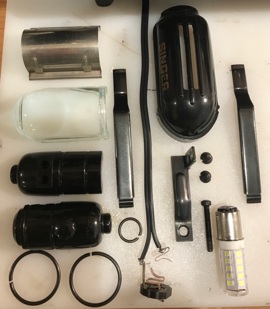
Note:  For this machine you will tie a knot in the wire before the terminal.  The metal barrels shown are for a Singer 128.

Using solder, tin the loop and the bit of wire back to the insulation.


While the solder is still hot, using smooth jaw pliers, squeeze the tinned wire and loop flat.  This will make it easier to screw the loop to the lug.

Use an awl to round the hole in the newly created terminal.


Use a mini file or sandpaper to debur the terminal if necessary.

_______________________________________________________________________________

Vintage Singer sewing machine old style AC plugs were not polarized; consequently the hot side of the circuit can run through either side of the machine.  The light socket can provide a shock even with the light switch off depending on how the non-polarized AC plug is inserted into the AC receptacle.


New AC plugs are polarized so it provides an opportunity to wire the machine in a safer manner.

I am providing a wiring diagram that depicts a polarized wiring path using a polarized AC plug.

It might be helpful to also note that polarity does not matter with regard to the controller and the motor.

I hope you have found this useful.
Michael

Wednesday, July 20, 2022

Vintage Singer No. 121379 Hand Crank anti-friction bearing Pinking Machine

 Downloadable Manual

 ••• SOLD •••
Vintage Singer
No. 121379 Hand Crank Pinking Machine (anti-friction bearing)
Near Mint - Cleaned and Lubricated
Circa 1930-1950s
Made In USA
I've been collecting sewing machines and accessories for a long time, but have never run across one of these.  A neighbor is moving and dropped off a bag of "Singer stuff because I now have a Brother," and this little beauty was in the bag.

It is a Singer No. 121379 Hand Crank Pinking Machine (anti-friction bearing).

Description:
The Singer Pinking Machine (No. 121379) was manufactured as an accessory for sewists to help finish seams and fabric edges long before sergers came onto the scene. Pinking shears were painful to use (still are for long periods of time) which inspired Singer to produce this hand crank pinking machine which allowed for painless and efficient pinking of larger volumes of fabric.

There's not a lot of information about them online, but they gained popularity in the 1930s and were manufactured for a few decades afterward.

Enjoy the following pictures.


Thanks for looking,
Michael

Tuesday, June 2, 2020

De-Yellowing Plastic

I found this article some years ago and have now tested it on several Bernina machines with great success.  Bernina's are very prone to yellowing on the back side and ends.

I'm attaching it to help others grappling with this issue.

The article is technical, but pursue reading, because the author goes onto describe it all in layman's terms using commonly available materials from the grocery store and the beauty supply store.

Hope this helps.

Good Luck,
Michael

De-Yellowing_Plastic.pdf

Monday, December 17, 2018

Jeep Dog Cushion

First attempt at creating an upholstered cushion...


*********************************************************************

Mountain rides are a passion for us and taking Cooper, our dog, is a must.  Unfortunately, in the CJ, there is no safe place for him.  Decided to make and upholster a cushion.  Watched a couple of great videos by Cechaflo on YouTube and got started.

Found some high density foam at the local auto upholstery supply.  They actually had a foam graveyard with all types of foam... for cheap.  This piece cost $10.  It is 6" thick and just fits my bandsaw which cut the sides and the curves very well.  Used an electric carving knife for the bevel.

To get the perfect size, I spray glued several pieces together.  Then marked reference points at midpoints on the sides and midpoints on the curves.  This will allow registration marks on the pattern to help keep panels from shifting while sewing.
Used rosin paper from the hardware store to cut patterns of the sides, pinned to foam to check fit and fine tune the curved sections.  Be sure to transfer all of the registration points to the paper.

It is important to pin all of the patterns on the foam together to make sure all of the seam lines meet.

Used weights to keep the pattern from shifting on the fabric, marked the reference points, then added 5/8" seam allowance.  Here you can see the zipper placket sewn to the head piece to form the band.

Used spring clips to hold the material together being careful to align guide marks.  Using a walking foot commercial sewing machine is helpful in keeping the material from shifting.  The cylinder arm also aids in sewing the curved and square corners.

Traced the actual pattern on the fabric, then added the 5/8" seam allowance.  It is then possible to sew right on the intended seam line rather than trying to follow the edge of the seam allowance.

The square corners were more challenging.  Sewing one side of each corner at a time allows more control rather than trying to continue around the corner in one sewing pass.

Decided to sew in one long zipper on three sides to make the cover easier to get on the foam.  Also checking fit prior to sewing on the bottom panel.

The clips are so much easier than pins.

For a first attempt, I'm happy with the fit.

Here is the cushion installed in the Jeep.  Overall size of the cushion is 6" x 12" x 28".  The back of the cushion rests against the step of the bed, snug fit between seats, and allows the seat belts to be fastened easily.  Next will be the harness.

Cooper approves this post.

Hope this helps you get your pal comfortably situated for those beautiful mountain rides together.

Mike