

This light fixture came with the Willcox and Gibbs chain stitch machine I received this week. It is caked with some unknown crud and the cloth wire insulation is badly worn. It is time to rewire.

The detents in the female half of the switch enclosure were made to snap into mating holes in the male half. This connection was never meant to be separated.

To separate the switch enclosure, use a drill bit slightly smaller (I used a 5/64ths bit) than the square detent. Very carefully drill the detent out taking care to stay in the center of the detent. We want to end up with a square hole again when finished. Also be careful not to drill any further into the enclosure than necessary to go through the detent so that the switch isn't damaged.


Gently work the two halves apart.

Slide the female half down the wire enough that you can pull the switch assembly from the male half of the enclosure.

Be careful not to destroy the fibrous insulating sleeve inside the male half of the enclosure.
Congratulations, that was the hardest part of this whole ordeal.

Next, pull the shade, wiggling back and forth, from the male half of the enclosure. There are spring clips underneath that hold the two parts together by friction. Be careful not to lose the spring clips.

Here you can see the little ball formed in the clip which protrudes through the base of the shade.


Once the switch assembly is removed, the screw terminals can be seen. This one looks like the person who originally assembled it was new to the idea of a screwdriver.

Here are all of the parts lined up. Now don't lose anything!

Before going any further, take a few minutes and clean up the detent drillings. We want the fixture to look as original as possible when finished.

Nicholson makes a small pack of miniature files which contains a tapered square file that is perfect for dressing the holes back to square.
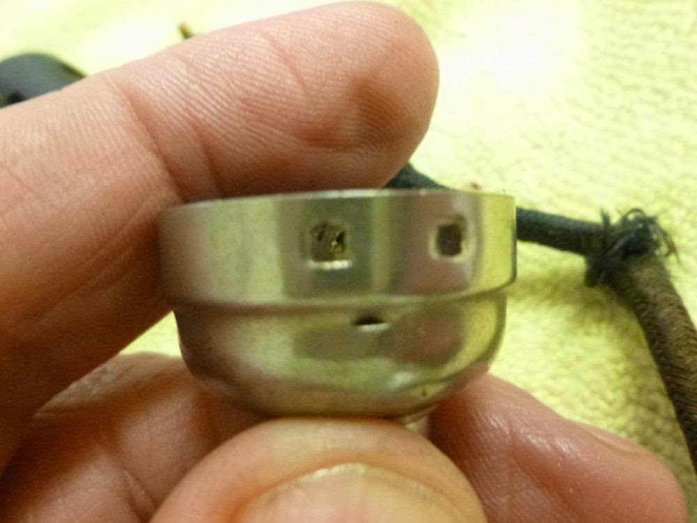

Use a half round file to deburr the inner curved surface. Go from the square file to the half round file several times until the outside looks square and the inner surface is free from burrs.

Polish all of the brass with a piece of Scotch Brite, then clamp a bit in a pair of needle nosed pliers and do the inside of the lamp socket; don't forget to hit the center tab at the base of the socket.

Use a pick to pry the tab up slightly so that it will make good contact with the lamp.

I use these products to clean, lubricate, and polish bakelite, bare metal, nickel plated metal, and electrical components.

Blow the switch out with compressed air, then spray the internal contacts with contact cleaner. Before the cleaner evaporates, work the switch five to ten times.
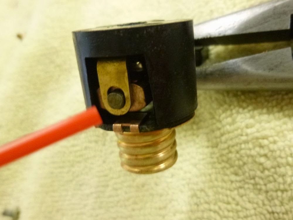
Then use a teflon based DRY lubricant on hinged parts. Dry lubricant won't attract dust and lint.

I clean bakelite parts with Mequiars Cleaner Wax, bare metal and nickel plated parts with Mother's Mag Polish. If the metal has rust, use 0000 steel wool lubricated with some oil to get down to the nickel. If the rust has gone through the nickel, it will still be silver. If the metal is too grimy for polish, I'll hit it with acetone. If that doesn't work, its time for brake cleaner. Once the rust, grime, and goo is off, back to the polish. The final buff is with 100% carnauba wax. Here are the parts all ready for the new wire and reassembly.

Ordered two feet of black rayon covered 18/2 wire from thestonedoor (seller on ebay) that matched the original lamp wire perfectly. Pull back the cloth outer sheath a couple of inches exposing the two conductors.

Strip back the insulation about 1.5 inches on each conductor and twist tightly.

Wrap the twisted wire around a 1/8" drill bit and then wrap the wire around itself about one and a half turns and clip the excess. Smooth the wire so that no loose strands are sticking up.

Brush a little flux on the newly formed wire loop which allows the solder to flow nicely. Lightly tin the wire all the way to the insulation. Try to avoid globs.

Using smooth jawed pliers, immediately flatten the loop all the way to the insulation.

Use an awl to round the opening in the loop.


Connect the wires using the original screws. If using a polarized plug, connect the white wire to the neutral side (the outer section of the socket) and the black wire to the center tab. It is a good practice to use the black wire as the hot and the white as the neutral and to always run the hot wire through the switch mechanism.

Slide a 1/2" length of heat shrink tubing all the way to the base of the socket to prevent the cloth outer sheath from fraying. Trim any frays.

As an added layer of protection, cut a strip of electrical tape and lay it on top of the wire in the side grooves and then another around the circumference of the socket.

Slide the socket into the fibrous insulating sleeve and then slide that assembly into the metal male half of the socket enclosure.

Run the female half of the socket up the loose end of the wire. I wasn't quite sure how I was going to keep the original look of the socket when I started, but upon seeing the series of square knock-outs all the way around the male half of the socket, it immediately became clear that, by aligning the square holes in the female half with the solid sections between the knockouts in the male half, the assembled enclosure would be hardly distinguishable from the original construction.

Clean the mating portions of the socket enclosure halves with rubbing alcohol and lightly sand with 320 grit sandpaper. Then squirt a little clear E6000 glue on a paper towel and get a small amount on the end of a q-tip.

Smear a thin layer on the inside of the female half of the socket. You don't want the glue to ooze out during assembly. Keep the glue away from the square holes to avoid unnecessary clean up.

Slide the halves together with the square holes evenly spaced from the switch arm and rotate until the square holes are centered over the solid metal areas. It looks almost like the original detents.

Making sure to keep the center line of both halves of the socket in line, lightly clamp (a rubber band can also be used) the halves together to prevent them from slipping apart while drying. Allow the glue to cure overnight.

Add some dry lube to both sides of the spring clips and place them on either side of the metal tube extension, align the hole in the shade with the extruded ball in the clip and push the shade onto the clips.

The extruded ball should present itself through the hole in the shade.

Attach the mounting clips to the metal flange at the base of the thread spool assembly, adjust the light fixture position, and tighten the mounting screw.


I assembled the light fixture to the sewing machine and positioned the cord over to the motor connection bay. Once I settled on the shape of the cord, the cord was marked at the edge of the connection bay with a piece of painters tape.
Remove the motor mounting screw and have someone hold the motor a few inches above the connection bay. Hold the tape against the edge of the connection bay and mark where the wire will be cut. Cut, strip, and twist the wires. Slide a piece of heat shrink tubing over the cloth sheathing, then wire nut the light cord to the existing motor connections. I used Ideal gray wire nuts; they are small and just accommodate three pieces of 18 gauge wire.
Carefully lower the motor back into the cradle in the base making sure not to pinch any of the wires and tighten the motor down to the base using the motor mounting screw.

One thing that I didn't think about because I typically restore Singers with the electrical connection from the wall coming first to the machine itself is what would happen when the connection comes first to the foot controller. Because there is no constant source of power for the light, it works on the same rheostat as the motor which means there is no light until the foot pedal is depressed and full light only when the motor is running faster than I typically sew. It does give an "old timey" feel to the machine however.
As an option, the cord to the light fixture could be left long, probably 6-9 feet with a separate electrical plug attached and plugged into the wall. This would allow the light to be on all the time and controlled by the switch on the fixture itself.
The wire that was attached to the light was short and gave me the impression that it was connected at the motor, but I can't say for sure and it doesn't describe it in the manual.
I'm going to leave the light connected to the motor as shown in the above photos because I don't want another long length of cord to deal with when setting up the machine to sew or when packing it away. It will also display better on the shelf.
Hope this helps,
Michael
Disclaimer:
Don't attempt the techniques explained in this article if you don't have electrical experience or are not certified in electronics. Doing so may result in electrical shock and/or death. If you decide to act on these techniques, you are doing so at your own risk. It is recommended to have your work checked by a licensed electrician or certified electronics expert.


